Magnetic Coupling - New Improved Design
What's the optimum layout for the magnets in the magnetic coupling for allowing a servo to operate through waterproof barrier. ?
After some prototyping and testing, I think I have a reasonable solution.
The main performance attributes of a magnetic coupling are:
- Ambiguity; and
- Holding Torque.
Holding torque can be maximised by having many magnets or many poles; increasing the strength of the magnets and reducing the distance between the coupling disks across the waterproof barrier.
Ambiguity refers to whether the coupling has multiple detent points. That is, can the external disk be forced into other stable positions, other than the intended position.
The problem of ambiguity can be reduced by reducing the number of poles.
A servo operating a rudder does not need to travel more than 180 degrees.
This means that ambiguity will be eliminated if there are two detent positions per 360 degrees (with one being eliminated by a 180 degree restriction).
This can be achieved with a 4 pole magnet layout, as shown in the following image.
 |
| 4-Pole Magnet Layout, with neighbouring magnets sharing the same orientation. This is my preferred layout. |
Tests were performed on a variation of the layout of magnets shown above, where the neighbouring magnets were setup with opposite orientation. The aim was to see if there was any measurable difference in performance.
 |
| 4-Pole Magnet Layout, with neighbouring magnets having opposite orientation. Holding torque reduced by 15%. |
The method of comparing holding torque of different magnet configurations was to use a simple spring scale.
The spring scale was pulled gently, while observing the maximum load before the coupling yields (or breaks free).
This provides relative values for comparing maximum torque values for different magnet arrangements. These are not actual torque values of course.
 |
| Measuring Relative Holding Torque using a Spring Scale. |
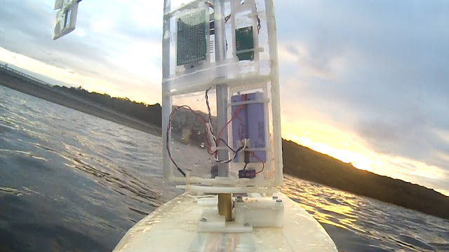
This is part of the ongoing development of a low cost autonomous oceangoing sailing drones, utilising a self-trimming wingsail. This is the Voyager series of sailing drones.


